Originally published at Techtarget.com
Redundancy can help a data center avoid downtime, but sometimes hidden flaws in the electrical design can still create a single point of failure.
Redundancy and uptime are practically synonymous in the IT industry. It is rare to see a new or renovated data center without redundant systems or components somewhere. Common examples include “dual-corded” servers and network switches with multiple redundant power supplies. The data center infrastructure typically includes redundant air conditioners, uninterruptable power supply (UPS) systems, generators and even redundant utility feeds to support a reliable facility. In this tip, I’ll uncover some potential single-point-of-failure flaws hidden in a data center electrical design and explain how to remedy or avoid these problems.
Does redundancy eliminate failure? Absolutely not! It should greatly reduce the chances, but never assume that buying duplicate components is all that is necessary. In many cases, the systems are designed and installed without full analysis of the entire chain. This means the owner has made large investments in costly additional power and cooling equipment that is vulnerable to one circuit breaker, valve or other single point of failure in the infrastructure that has either been overlooked or misunderstood.
The following examples are all electrical, and are taken from actual projects. They are disguised somewhat to protect the guilty, but still illustrate the potential flaws that can render otherwise robust redundant hardware useless. Also shown are ways the vulnerabilities might have been remedied, but it must be emphasized that there is never one solution to a design problem! These remedies are shown for illustration only, and are not meant to dictate how a particular design should be implemented.
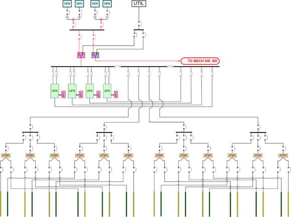
Illustration 1
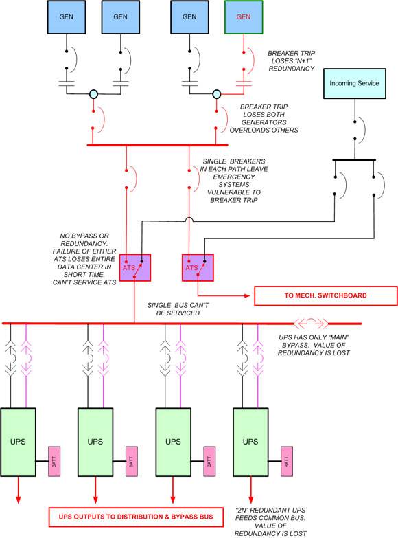
Illustration 2
Multiple vulnerabilities
Illustration No. 1 shows an overall power system with N+1 generator redundancy, 2N UPS redundancy and a complete 2N array of overhead power busways to support dual-corded servers. There are a number of flaws and failure exposures in this design, but we’ll concentrate on the four major ones. Illustration No. 2 magnifies and annotates the areas of most concern, which are highlighted in red. Subsequent illustrations show each of these conditions individually.
False generator redundancy
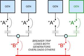
Illustration No. 3 shows the generator design, which has N+1 capacity redundancy. (For this example, the generator marked in green is considered the redundant unit, but in actual practice, any one of these four generators would actually be redundant to the other three.) In other words, if any one generator fails, the remaining three generators are sized to handle the maximum total data center load. No problem.
But wait. In this case, the generators are “packaged” in pairs, which leaves the redundancy dependent on either of the two “B” circuit breakers as highlighted in red. Each individual generator is protected by an “A” breaker, and if one of them trips, the redundancy remains. If either of the “B” breakers trip, however, the two associated generators go offline and half of the generating capacity is immediately lost. Assuming that three of the four generators are actually needed to support the load, this will result in overload of the remaining two generators, and/or the other “B” circuit breaker, which will shut down all generator power in very short order. That would be a serious problem for the data center.
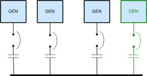
One possible remedy is shown in illustration No. 4. This is a more conventional arrangement, where generators are individually connected to a common bus in the paralleling gear, which avoids the single point of failure. Since this is an N+1 design, there is still a small vulnerability in that the paralleling gear cannot be serviced without losing the protection of the backup generators. It would require a fully 2N design to avoid this condition. But if switchgear maintenance is scheduled when no storm conditions or local excavations are planned, the chances of a utility failure and the need for generator backup are greatly reduced without incurring the added cost of a 2N design.
Automatic transfer switch bottlenecks
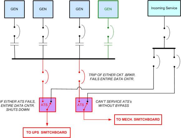
Designs with backup generators are completely dependent on automatic transfer switches (ATSes), which sense the power failure, start the generators and switch the load to them when the generator power is stabilized. Despite all the other redundancies in this design, a failure of either ATS or its circuit breakers, as shown in illustration No. 5, will bring down the entire data center. For example, if the ATS feeding the UPS switchboard fails, the data center will shut down when the UPS batteries are exhausted. Similarly, if the ATS feeding the mechanical switchboard fails, the data center will shut down when temperatures become unacceptably high. In actual practice, this is usually a sequential event. High-density computers, such as blade servers, will shut down first, and other equipment will follow in relation to heat rise and location in the room. Total shutdown will occur when the UPS overheats, which may happen ahead of actual equipment overheating. Even though ATSes are generally highly reliable devices, the underlying problem is that neither of these is equipped with a bypass, so it is impossible to maintain them, opening the door to failure at some point in time.
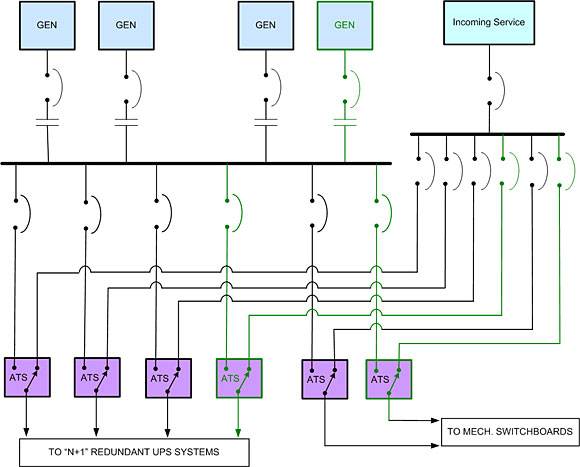
One possible solution is shown in illustration No. 6. Since the UPS system is now designed as N+1 redundant, each UPS can be fed through a separate, much smaller ATS. This is somewhat more expensive, but not substantially so, since each ATS is of lower capacity. The added cost of redundant ATS units is easily justified in a high-reliability data center power system.
Likewise in illustration No. 6, the mechanical systems could be divided and fed through two ATSes. This requires that the cooling systems be split into two sections (or even better, three sections with three ATSes). This is not illustrated, but would require duplicate (although smaller) mechanical switchboards and possibly some further duplication of components in the cooling system. Unlike the electrical backup, cooling system redundancy can be under-sized and still maintain an acceptable temperature for a period of time in the event of a partial failure. Temperatures will rise somewhat, of course, but an examination of the ASHRAE TC 9.9 Thermal Guidelines will confirm that the hardware can run for several days, considerably above the recommended temperature, without real harm and without voiding warranties. So splitting the cooling systems, even in an N+1 design, can be a good way to protect your investment in expensive redundant components.
UPS redundancy and maintenance bypass
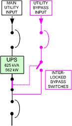
Another difficulty with this data center power design is that the UPS bypass is on the main bus. This requires putting the entire redundant UPS into bypass and running the data center on street power if work has to be done on any UPS main connection, which is not an advisable approach. In order to do major work on a UPS, the UPS’s internal maintenance bypass is insufficient. An external “full wraparound” bypass, as shown in illustration No. 7, takes the UPS and its transformers completely out of the power chain so that it can be completely opened and serviced if necessary.
Under-sized circuit breakers
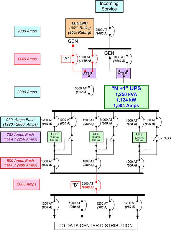
Illustration No. 8 is an N+1 UPS with a very hidden single point of failure flaw. The problem with redundant designs is that they can be loaded to higher than their intended capacities if power usage is not properly monitored. If power is not well managed, it’s even more likely that the three phases of the power system will be significantly out of balance, with one phase carrying an abnormal percentage of the load. In either case, it is easy for the redundant UPS to end up supporting part of the normal load without anyone realizing it. If future expansion modules have been pre-planned, it is also not uncommon for redundant capacity to be intentionally utilized for a period of time, simply because funds are not available for the additional module even though power growth has occurred.
In illustration No. 8, the UPS system is made up of three 625 kVA (562 kW at 9.0 power factor) UPS modules. The intent is for the UPS to support a maximum of 1,250 kVA, or 1,124 kW, of load. Each UPS would normally carry only one-third of the load, with any two of the UPS modules ready to absorb half the load in the event one of the other units fails or is shut down. But circuit breakers operate on current draw or amperage. Further, unless they are specified as “100% rated” (and only one of the breakers in this design is), circuit breakers are only designed (by code) to carry 80% of their rated “trip” current on a continuous basis. Exceeding that draw for an extended period of time will eventually cause a breaker to open, shutting down power.
There are two such potential points of failure in this design (highlighted in red). Circuit breaker “B” is rated at 2,500 amps trip, or 2,000 amps continuous load. However, we will concentrate on Breaker “A” ahead of the ATS, since an overload of breaker “B,” while possible for the same reasons as will be described, is much less likely.
Circuit breaker “A” is in the main power chain, and is rated to carry 1,440 amps of continuous load (1,800 x 80%). However, just two of the UPS modules running at full capacity will draw at least 1,504 amps (which is calculated purely on UPS capacity and does not even account for incoming power efficiency losses). If the load reaches close to design capacity, even if on only one unbalanced phase leg, breaker “A” will trip, cutting power and transferring the load to the generator, which has the same single point of failure vulnerability plus the others described above.
How can such a seemingly obvious situation occur in a design done by a professional engineer? The answer is twofold. First, breaker sizing is initially based on several factors, including recommendations of equipment manufacturers and code issues. But the engineer may then become immersed in the complex, challenging, and critical task of breaker coordination and fault current (short circuit) studies, and fail to see the proverbial forest for the trees. A peer review of these complex and critical designs is never a bad idea.
Confusing drawings
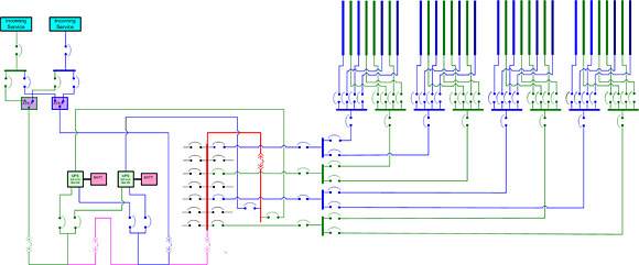
Illustration No. 9 shows a design with full 2N redundant utility power, 2N redundant UPS systems and complete dual-feed cabinet distribution. Normal and redundant paths are shown in blue and green. The bypass path is magenta. The way this circuit is drawn camouflages the flaw, but the UPS path, with its single point of failure, is highlighted in red. The entire data center, despite the substantial cost of all this duplicate equipment and the switchgear to support it, is dependent on one power bus and one circuit breaker. Making it worse is the fact that the critical path breaker is part of the bypass circuit, so it is electrically operated. Therefore, it is vulnerable to both a normal breaker trip and a problem in the control circuitry.

Illustration 10
Simply re-drawing the circuit (Illustration #10) not only highlights the considerable effort taken to assure redundancy in the incoming power, UPS, transfer switch and distribution systems, but also how totally dependent all this hardware is on one circuit breaker.
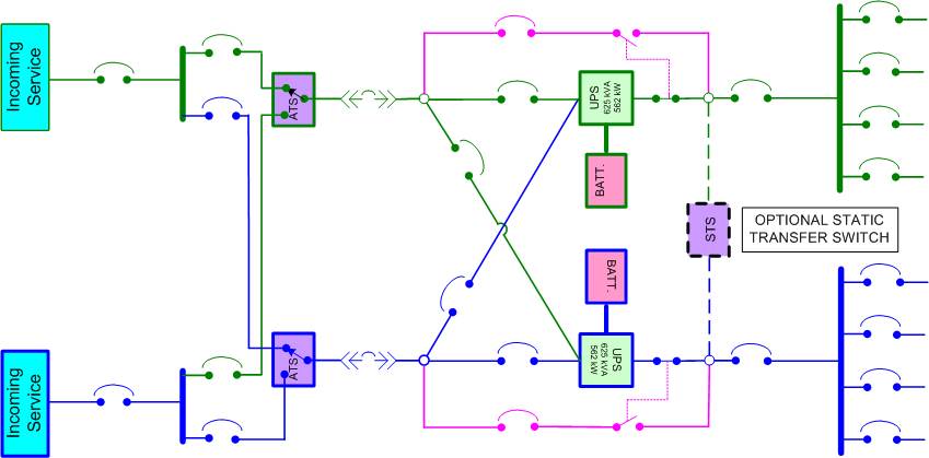
Illustration 11
Illustration No. 11 shows the distribution approach that is more common today in a 2N power design. With 2N systems, there is little reason to combine the power into a single output bus since virtually all computing hardware is now dual corded and can run from either power source if the other fails. Equipment that is single corded can be protected with local, rack-mounted static transfer switches (STSes) or, if a “belt and suspenders” approach is preferred, a large STS can be installed between the UPS output feeds as is shown in this illustration as an option. (Many people regard large STSes as another potential single point of failure and no longer use them. This is a matter of preference.) Either way, the additional cost will be only a small percentage of the investment in what is intended to be total redundancy protection.
Check designs and test carefully
Redundancy is expensive. It is justified only by a management conclusion that taking steps to better ensure the continuous, reliable operation of the data center is worth the monetary investment in additional hardware and space. But redundancy alone may provide a false sense of security if it is not designed to remove single points of failure that can easily negate its purpose and value. The designs are usually complex, which always opens the door to inadvertent oversights. It is valuable to have a fresh set of eyes reviewing redundant designs before making the substantial investment in duplicate equipment.

